Introduction
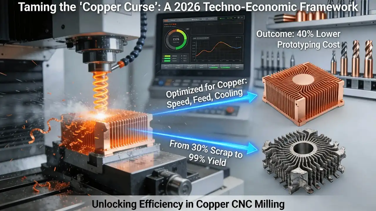
Developing prototypes for next-generation electronics, high-performance heat sinks, or precision medical devices often brings engineers face-to-face with the “Copper Curse.” This material, prized for its superior electrical and thermal conductivity, becomes notoriously “gummy” during machining, leading to drastically shortened tool life, inconsistent surface quality, and a high propensity for thin-wall parts to warp. These challenges can cause the cost of a copper prototype to soar 40% above that of an equivalent steel part, severely hampering the pace of innovation.
The root cause is that many manufacturers lack targeted strategies for the unique cutting physics of copper alloys. Applying generic parameters meant for steel or aluminum leads to material adhesion, built-up edge, and excessive heat, directly resulting in high scrap rates, lengthy manual post-processing, and unpredictable project budgets. This article provides a 2026 “Techno-Economic Optimization Framework for Copper CNC Milling” to transform these unpredictable costs into manageable variables.
Why Does Pure Copper “Fight” the Cutting Tool? The Science of Material Adhesion
Copper’s greatest assets — its high ductility and thermal conductivity — are the very properties that make it notoriously difficult to machine. In pure copper (C11000), the material deforms rather than shears cleanly, leading to long, stringy chips that readily weld onto the cutting tool’s edge. This forms a built-up edge, which dynamically alters the tool’s geometry, degrading surface finish, accelerating wear, and causing inconsistent dimensions. This fundamental challenge varies with alloy: brass (C26000) is more brittle and generates smaller chips, while beryllium copper offers better machinability at a premium.
- The Material Science of Cutting Copper: The phenomenon of built-up edge is a direct consequence of copper’s physical properties. Authoritative references like the ASM International Handbook detail the mechanical and thermal characteristics that explain this behavior. Pure copper’s low shear strength and high thermal diffusivity mean heat generated at the cutting edge rapidly conducts into both the chip and the workpiece, softening the material and promoting adhesion to the tool. This scientific understanding is the foundation for any effective machining strategy.
- Consequences of Uncontrolled Adhesion: When left unmanaged, material adhesion wreaks havoc on both quality and cost. A built-up edge acts as a blunt, irregular extension of the cutting tool, scraping rather than shearing the workpiece. This results in a poor, torn surface finish, rapid dimensional inaccuracy, and a catastrophic reduction in tool life, sometimes by 60% or more compared to machining steel. The high scrap rate and need for frequent tool changes are primary cost drivers.
- The Path to a Systematic Solution: Overcoming this challenge requires a holistic, engineered approach. It is not about finding a single “magic” speed or feed, but about orchestrating tool geometry, coatings, cooling, and parameters into a cohesive system. To explore a complete methodology for tackling adhesion through specialized tooling, cooling strategies, and parameter optimization, a comprehensive resource is invaluable. A deep manufacturer’s guide on copper CNC milling services provides extensive real-world data and solutions.
How Can You Machine a Thin Copper Heat Sink Without It Warping Like a Potato Chip?
Thin-wall copper parts are exceptionally susceptible to deformation from two primary forces: machining stress and thermal gradients. Cutting forces can induce local stress that exceeds the material’s yield strength, causing permanent distortion. Simultaneously, the high thermal conductivity of copper can create a steep temperature differential between the cutting zone and the bulk of the part, leading to thermal expansion and contraction that manifests as warping.
1. Strategic Process Planning to Counteract Forces
Mitigating this requires a strategy that balances internal stresses and manages heat. A symmetrical machining strategy — removing material evenly from both sides of a thin wall — prevents the buildup of unbalanced residual stress. The use of multi-point, flexible fixtures minimizes clamping pressure and distributes holding force to avoid distorting the part before cutting even begins. This proactive approach is more critical than relying solely on machine precision.
2. Actively Managing the Thermal Environment
Heat management is non-negotiable. Employing targeted, high-pressure coolant or even cryogenic cooling (like cold air or nitrogen) directly at the cutting zone is essential. This rapidly extracts heat, preventing it from soaking into the workpiece and establishing a damaging thermal gradient. The goal is to maintain the part as close to ambient temperature as possible throughout the machining cycle, a key pillar of successful Process Optimization.
3. Designing for Manufacturability from the Start
The battle against distortion is won in the design phase. Engaging with manufacturing experts early allows for Design for Manufacturability feedback that can suggest slight increases in nominal wall thickness, the addition of strategic stiffening ribs, or the orientation of critical features to align with the strongest tool paths. This collaboration ensures the design of custom copper parts is inherently more robust and economical to produce.
Where Does the Money Go? A Transparent Cost Breakdown for Copper CNC Milling
To cut costs intelligently, you must first understand their composition. A true cost model for copper machining goes beyond the per-part quote. It includes direct costs like raw material (beryllium copper can cost multiples of brass) and tooling consumption, which is disproportionately high due to adhesion. It also includes indirect costs: programming and machine time (increased by complex anti-distortion strategies), and post-processing/quality inspection to verify delicate features.
1. The Leverage Point of Tooling Optimization
Tooling is often the highest variable cost and the greatest opportunity for savings. A shop using generic carbide end mills might see tools fail after 15 parts. By switching to copper-optimized tool geometries with specialized coatings (like AlCrN or diamond-like carbon), tool life can be extended to 45 parts or more. This single change can directly reduce the per-part tooling cost by 30%, a massive impact on overall Business Efficiency.
2. Analyzing the Full Cost Driver Landscape
Building this cost model reveals the interconnectedness of decisions. A design change that reduces machining time by 20% might save on machine hours but could increase material cost if it lowers yield from a standard stock size. Understanding these trade-offs allows for informed decision-making that minimizes the total project cost, not just an individual line item. This analytical approach is fundamental to managing CNC milling cost factors effectively.
3. From Analysis to Economical Production
Therefore, the journey from a cost-optimized design to reliable, high-volume production requires a partner with integrated expertise. Translating a deep understanding of costs and processes into thousands of consistent, affordable end products depends on a manufacturing partner capable of holistic control. A capable CNC milling services partner that can manage the journey from material science to finished part is essential for this transformation.
Case Study: From 30% Scrap Rate to 99% Yield in EV Motor Component Milling
A compelling example of this framework in action comes from electric vehicle manufacturing. A client needed precision-machined copper end caps for a motor assembly. The initial challenge was severe: thermal deformation during machining caused flatness to exceed a tight 0.05mm tolerance, resulting in a catastrophic 30% scrap rate. The high cost of the copper alloy made this waste unsustainable.
1. Diagnosing the Root Cause and Engineering a Solution
Analysis pinpointed two issues: concentrated heat at the cutting interface and uneven clamping stress. The solution was a two-pronged, engineered approach. First, a novel low-temperature cutting strategy was implemented, using a specialized coolant and parameters to minimize heat generation. Second, a custom 12-point locating fixture was designed to hold the part with uniform, minimal pressure, eliminating distortion from clamping.
2. Quantifiable Results and Systemic Implementation
The outcome was transformative. The implemented changes brought flatness consistently under 0.015mm, well within spec. The scrap rate plummeted, and the first-pass yield soared to 99.2%. This generated six-figure annual savings for the client. The case underscores that solving such challenges provides powerful Industry Insights and delivers Custom Solutions with direct bottom-line impact.
3. Institutionalizing Success Through Quality Systems
Achieving and, more importantly, sustaining a 99%+ yield rate requires more than a one-time process fix. It demands the disciplined, repeatable framework of a quality management system. Standards like IATF 16949 mandate statistical process control, standardized work instructions, and continuous improvement protocols. This systemic approach is what turns a successful pilot into guaranteed, day-in, day-out production reliability for a copper milling manufacturer.
The Buyer’s Checklist: 5 Questions to Vet a True Copper Machining Specialist
Selecting the right partner for copper components requires moving beyond general capability claims to probing specific, copper-centric expertise. Use this checklist to separate true specialists from generalists. First, ask for evidence of process knowledge: “For my specific copper alloy, can you share a sample of your optimized cutting parameter database and the make/model of the specialized tooling you recommend?” This tests their foundational technical depth.
- Probing Thermal and Mechanical Process Controls: Second, investigate their approach to the core challenges: “How do you measure and control workpiece temperature during machining? Please describe your specific cooling strategy for copper.” Third, target their deformation protocol: “For the thin-wall features in my design, what is your step-by-step process to prevent distortion?” Their answers should reveal a methodical, physics-based strategy, not vague assurances.
- Demanding Proof of Performance: Fourth, and most crucially, request concrete proof of past performance. Ask: “Can you provide the full first-article inspection report (including raw CMM data) for a recent copper project of similar complexity?” A confident specialist will have this data ready, demonstrating their commitment to transparency and their ability to deliver to print. This due diligence is your best tool for selecting a reliable CNC copper machining supplier and understanding a copper parts quote.
- The Partner as an Extension of Your Team: The right partner functions as an extension of your engineering department. Their responses should demonstrate not just the ability to make the part, but the experience and curiosity to optimize how it’s made. Their mastery of copper’s quirks transforms them from a simple vendor into a strategic asset, providing the Technology Guide and execution needed to de-risk your project and control costs.
Conclusion
In the relentless pursuit of high performance, miniaturization, and thermal management, copper has become an indispensable yet challenging material. By moving beyond generic machining approaches and adopting a techno-economic framework specifically engineered for copper’s unique properties, manufacturers can shatter the “high-cost, high-difficulty” stereotype. This is not merely about reducing a part’s price tag; it is about mastering project risk, accelerating development cycles, and converting the inherent advantages of copper into definitive product superiority and cost advantage in a competitive market.
FAQs
Q: What is the most cost-effective copper alloy for prototyping that still offers good conductivity?
A: For prototyping where conductivity is key but cost matters, C11000 (ETP Copper) offers excellent conductivity at a lower price. For better machinability with slightly reduced conductivity, C26000 (Cartridge Brass) is a popular, more economical choice as it produces smaller chips and causes less tool wear.
Q: How does the surface finish from CNC milling copper compare to other processes like grinding or polishing?
A: With optimized milling, surface finishes of Ra 0.8 – 1.6 μm are achievable. For mirror-like finishes (Ra < 0.1 μm), subsequent processes like mechanical polishing or electropolishing are typically required. Milling provides the foundational geometry, while finishing enhances aesthetics and specific surface properties.
Q: What is a realistic minimum wall thickness for CNC-milled copper parts?
A: For most copper alloys, 0.5mm to 0.8mm is achievable with careful strategies. For softer pure copper, designing walls above 1.0mm is safer. Thinner features increase distortion risk, require specialized fixturing, and raise costs significantly.
Q: Can you machine complex internal features, like cooling channels, inside a copper part?
A: Yes, but with limits. CNC milling can create internal cavities and channels using long-reach tools or multi-side access. However, truly enclosed 3D channels (e.g., conformal cooling) are not possible with milling alone and are better suited for additive manufacturing. Milling excels at straight or simply curved internal passages.
Q: How quickly can I get a quote and first articles for a custom copper prototype?
A: Using an online system, a detailed quote is often provided within 24 hours of CAD submission. Lead time for first articles typically ranges from 3 to 7 business days, depending on complexity and alloy. Expedited services are commonly available for urgent prototyping needs.